
How it is built
Core Elements
How the tunnel, atmospheric gateway, geothermal system, power system and AstroLiner are designed.
- Length. Approximately 2,050 km.
- Cross-section. Circular (Ø18 m), designed for the shuttle and stable magnetic levitation.
- Tunnel depth. Up to approximately 8 km, with greater depths possible if geological and thermal conditions permit. The allowable depth can be established only after detailed geological exploration: drilling along the route, building a temperature profile, and assessing rock stress, fracturing and hydrogeology. The lower the temperature and heat flux in the deep formations—provisionally up to about 200–250°C—the wider the range of buildable depths and the greater the freedom to optimize curve radii and transition sections. That freedom reduces peak g-loads and dynamic loads while preserving the target speed.
- Construction. A combined layout. The approximately 330 km starting section is a shallow underground straight descending toward the gateway to simplify initial acceleration. The main section is a deep-buried or underground tunnel providing thermal stability, vacuum isolation and safety.
- Route geometry. An S-shaped curve begins after approximately 330 km.
- Descending arc. A radius of approximately 6,300 km carries the tunnel gradually downward to establish the required angle.
- Ascending arc. A radius of 2,500–3,500 km brings the tunnel to the gateway at approximately 5–6° above the horizontal. The radii keep centripetal acceleration at hypersonic speed below 4g.
- Vacuum system. Segmented. Each approximately 50 km segment is autonomous, with its own vacuum pumps, sensors and emergency valves.
Acceleration system
The shuttle is accelerated and stabilized through interaction between its onboard superconducting magnets and distributed linear electromagnetic drives, or windings, installed in the tunnel. The drives are segmented passive windings made from conventional conductors such as copper or aluminium and require no cryogenic cooling.
- Initial tunnel section (0–330 km). The drives are located mainly beneath the guideway. They generate the field for levitation and initial acceleration at 4g and actively compensate for gravity.
- Middle tunnel section (330–2,000 km), especially the S-curve. Drives surround the tunnel perimeter, providing precise acceleration, force-centering the shuttle at hypersonic speed, and stabilizing it through curves. Reinforced, structurally redundant winding materials are used along the floor of the final high-radial-load portion. From 330 to 2,000 km, acceleration tapers from 4g to 0g while the shuttle reaches approximately 11 km/s by the end of the trajectory.
- Final section (2,000–2,050 km). The last 50 km stabilize and center the shuttle before it enters the atmosphere through the atmospheric gateway. No acceleration is applied in this section.
Pulsed power from GATES substations is delivered to selected winding segments in exact synchronization with the shuttle’s position, producing a travelling magnetic field. Interaction with the onboard magnetic field accelerates the shuttle. This architecture keeps the tunnel maintainable and transfers the most advanced components to the reusable vehicle.
It solves the ‘last-mile’ problem.
Location and construction
The gateway complex stands on the summit plateau of Mount Mohi, approximately 3,400 m above sea level in the Democratic Republic of the Congo. A broad southern plateau 16 km farther south is reserved for future expansion and could hold dozens of parallel gateways. The complex is a massive structure with a primary mechanical closure and gas-dynamic-barrier systems. In effect, it is a stationary ground-based jet engine with a triple annular nozzle aimed upward—not to accelerate a vehicle, but to displace the atmosphere and create a buffer as the shuttle enters it.
Gas-dynamic barrier
This is the principal working element. Several seconds before the shuttle arrives, the system begins producing a conical supersonic gas flow directed outward along the tunnel axis.
- Source and construction. Three independent concentric annular jet-engine belts—or equivalent hypersonic ramjet belts in the same three-stage arrangement—surround the gateway exit and burn an air–hydrogen mixture. Hydrogen is produced on site by electrolysis. Triple redundancy makes the system fault-tolerant: any two belts are sufficient to form an effective barrier, so one of the three may fail without disabling the gateway. Each belt has independent fuel delivery, control and ignition. The belts are arranged around the exterior in successively recessed steps from the smallest to the largest; the mechanical closure sits inside the gateway behind them. The belts can therefore start before the mechanical closure opens.
- Principal functions.
1) Establish outward-directed pressure that protects the tunnel vacuum while the shuttle passes.
2) Displace and preheat the atmospheric air ahead of the gateway, establishing a controlled gradient across the vacuum–atmosphere interface.
The gas-dynamic barrier is not an aerodynamic shield and does not screen the shuttle from the atmosphere. It extends the transition in time, converting the nearly instantaneous, microsecond-scale impact of cold stationary air into a distributed millisecond-scale load against a heated co-flowing stream. Total aerodynamic force is not reduced, but jerk and high-frequency loading fall sharply, reducing local structural-failure and thermal-shock risks.
- Flow shape. An outward-flowing cone with an ellipsoidal section matching the tunnel and shuttle, tens to hundreds of metres long, produced by three rows of annular nozzles in the gateway’s jet belts.
The gateway does not require a geometrically perfect, stationary or strictly axisymmetric cone. Its operating state is inherently dynamic and permits temporal and spatial variation in flow shape, density and velocity.
The sole rigid operating condition is a positive outward pressure and momentum gradient throughout the shuttle’s exit, completely preventing atmospheric air from entering the tunnel. The system must also prepare the exit region gas-dynamically and thermally. Together these requirements make the gateway substantially more reliable and feasible.
Flow shape is therefore an adaptive parameter rather than a target in itself. It is optimized in real time by integral quantities—pressure, mass flow and momentum—not by a fixed geometry.
- Scalability and testing. Unlike the thousand-kilometre accelerator, the gateway is modular and readily scalable. Stable supersonic-cone formation, synchronization and jet-belt operation can be proven on fully functional 1:5 or 1:10 physical test stands, retiring the principal technical risks before full-scale route construction begins.
Safety system
Hydrogen imposes stringent fire and explosion-safety requirements. The gateway therefore uses redundant hydrogen-leak detection, inert nitrogen purging of lines, explosion-protected equipment, physical separation of electrolysers, storage and engine belts, and directed ventilation ducts that discharge any release safely away from personnel and critical infrastructure.
Dimensions and launch mass
Length approximately 150 m; ellipsoidal section approximately 10 × 15 m. The hypersonic-wedge shape is optimized to minimize drag and heat load while piercing the atmosphere.
- Optimal launch mass: approximately 15,000 metric tonnes.
A 15,000-tonne shuttle is the engineering and economic optimum: a practical middle ground between physical limits and industrial feasibility.
| Criterion | Lower range (<8,000–10,000 t) | Optimum (15,000 t) | Upper range (>20,000–25,000 t) |
|---|---|---|---|
| Aerodynamics and g-loads | The atmosphere dominates. Drag Fd = CdρAv²/2 produces high acceleration a = Fd/m, demanding complex active stabilization and causing peak heat loads. Cd is the aerodynamic drag coefficient. | Inertia dominates. Atmospheric drag produces brief initial loads of approximately 3–6g for up to five seconds, allowing simpler shock absorption and thermal protection. | Loads decline only slightly, while other factors erase the benefit. |
| Thermal regime | Low heat capacity. Small mass m causes rapid temperature rise ΔT = Q·t/(m·c), requiring extreme active cooling. | High thermal inertia. The massive structure absorbs and disperses peak heat during the brief atmospheric passage, permitting a combination of passive and active thermal protection. | Heat capacity increases, but removing heat from the massive structure becomes a separate problem. |
| Launch energy | Required energy E = ½·m·v² is manageable, but does not offset the other disadvantages. | Balanced requirement. Acceleration to 11 km/s requires approximately 9×10¹⁴ J (about 252 GWh), within the capability of the distributed GATES and storage system. | Energy rises linearly, forcing a disproportionate and uneconomic increase in power and storage capacity. |
| Construction and logistics | Buildable, but without the decisive advantage of an ‘inertial ram.’ | Compatible with existing technology. Its dimensions and mass fit modern shipyard docks, welding methods and transportation practice. | Structural stiffness falls; natural-vibration, assembly and delivery problems grow. Costs rise faster than linearly. |
| StarRoad philosophy | It remains a ‘light vehicle’ vulnerable to the atmosphere. | It realizes the ‘inertial ram’ approach: the atmosphere becomes a brief disturbance overcome through mass and strength, not an enduring barrier. | It becomes an industrially unmanageable undertaking, eliminating economies of scale. |
- Physically, it is above the approximately 10,000 t threshold at which inertia begins to dominate aerodynamic effects.
- Energetically, it does not drive an exponential increase in infrastructure requirements.
- Technologically, it remains within scalable industrial practice: shipbuilding and heavy engineering.
- Economically, it balances lower delivery cost through scale against capital-cost constraints.
The chosen mass is therefore a calculated optimum that makes StarRoad physically feasible and economically defensible.
Internal arrangement and systems
The interior is designed as a multilevel longitudinal structure, with functions separated vertically through the hull.
- The lower and aft hull are devoted to power and propulsion: the onboard reactor, heat exchangers, active-cooling loops, power converters, energy stores, coolant mains and marine-propulsion equipment. This lowers the center of mass, improves stability in hypersonic flight, glide and splashdown, and simplifies thermal and radiation shielding of the upper compartments.
- The superconducting levitation and stabilization system runs along the sides and partly beneath the hull. Superconducting modules sit directly behind the outer skin and thermal-protection layer, minimizing the gap to the tunnel’s passive windings. Magnets are placed:
- along both sides for the full hull length, including the upper and middle zones up to the sliding-door line;
- across the middle and aft underside;
- outside the deployment paths of the main wings and mechanical bays.
This distribution produces a uniform magnetic field, strong hypersonic stability and tolerance of localized damage.
- The middle hull contains the folding-wing bays and their load-bearing attachment frame. The main wings retract into the hull and remain isolated from the power and cargo compartments. Small deployable control wings occupy the forward middle section of the nose for trajectory correction and stabilization during transitional flight.
- The upper hull contains a universal replaceable payload module. Dimensions, mounting points, mass and permissible center of gravity are standardized; the module may carry cargo, propellant, passengers or a combination. It is installed and removed in the dock before launch and may also be removed in orbit after the upper doors open. An integrated hydraulic or electromechanical lift and guide system deploys and extracts modules automatically in microgravity without crew intervention.
- The sliding upper doors are not primary structural members. They form an aerodynamic fairing and provide orbital access. Folding thermal-control radiators are integrated into the doors; after the doors open and lock, the panels deploy automatically and receive coolant to reject excess heat into space.
- The shuttle nose has a multilevel functional arrangement:
- upper nose: bridge, flight-control, navigation and communications systems;
- middle nose: mechanisms for the small deployable wings and control surfaces;
- lower nose: cryogenic fuel and coolant tanks arranged for low hydraulic resistance and the fastest possible coolant delivery to the nose’s active-cooling system during atmospheric penetration.
This arrangement shortens thermal and hydraulic paths, reduces the nose’s thermal lag and improves thermal-protection reliability during the most demanding flight phase. Overall, the vehicle is a rigidly organized, scalable and modular architecture optimized for hypersonic launch, orbital work, autonomous navigation at sea and repeated operation without major hull disassembly.
Hull thermal protection
The nose and underside use a multilayer composite-metal thermal-protection system designed for extreme thermal and dynamic loads during hypersonic flight and subsequent splashdown. It combines passive and active elements:
- an outer heat-resistant layer capable of withstanding brief exposure to temperatures of several thousand degrees and intense radiative heating;
- a load-bearing metal sublayer that carries mechanical and vibration loads;
- active-cooling circuits that remove heat from the most heavily loaded zones, especially the nose and forward edge of the underside;
- replaceable ablative elements in local critical zones, designed to wear in a controlled manner without damaging the main structure.
The system also accounts for thermal shock when the heated hull meets ocean water, including steep temperature gradients and cyclic thermal stresses. Segmentation and modular replacement of the highest-load elements during scheduled servicing improve maintainability and reusable service life.
Wings
Two pairs of deployable wings provide stabilization, glide and landing control. They deploy after the shuttle reaches the rarefied upper atmosphere.
- The forward pair corrects trajectory, stabilizes pitch and roll, and damps dynamic disturbances. It deploys in the rarefied upper atmosphere for gliding flight.
Each forward wing:
- root-to-tip span: approximately 35 m;
- root/tip chord: approximately 14/7 m;
- area: approximately 360–400 m².
- The aft pair forms the shuttle’s main aerodynamic surface.
Each aft wing:
- root-to-tip span: approximately 100 m;
- root/tip chord: approximately 14/7 m;
- area: approximately 1,000–1,100 m².
Total wing area is approximately 2,800–2,900 m². The lifting-body fuselage adds roughly 20–30% to the effective aerodynamic area.
In subsonic flight the combined configuration provides an estimated lift-to-drag ratio of L/D ≈ 9–13, supporting stable gliding and controlled landing-site selection. Typical glide and splashdown speeds are estimated at 90–120 m/s (about 320–430 km/h). At these speeds, landing safety depends less on absolute horizontal speed than on vertical speed at contact, angle of attack and glide-slope profile.
Parachute systems
A reusable parachute–parafoil system reduces splashdown loads and widens the acceptable landing window. It serves as a conditionally deployed soft-landing circuit.
- Architecture and placement. The system has two parafoil stations:
- one in the upper aft hull;
- one in the upper forward hull, immediately behind the nose.
Each station uses an N+1 arrangement—one primary and one reserve parafoil—with independent packing and extraction lines. Loads enter the structural frames through a transverse attachment line rather than a single point, reducing local peaks and improving pitch-and-roll stability. Longitudinal separation prevents the canopies from interacting or fouling each other.
- Area and operating mode. The parafoils do not carry the vehicle’s full weight. They damp vertical speed during the final phase and shape a gentle contact. Indicative values:
- area of one primary parafoil: approximately 4,500–6,000 m²;
- combined active area with both parafoils deployed: approximately 9,000–12,000 m².
Target vertical speed at contact: Vz ≈ 1 m/s.
- Deployment criterion. The parachute–parafoil system is used only when required. The landing algorithm evaluates total g-load, the vector sum of aerodynamic, inertial and hydrodynamic components:
- if predicted total load at contact does not exceed 4g, the shuttle lands on its wings without parafoils;
- if the predicted load may exceed 4g, the system deploys and reduces vertical speed to the target, producing a soft gliding contact.
- Reusability. Parafoils, lines and attachment hardware are designed for repeated use with scheduled inspection, drying and replacement of wear parts, without dismantling the hull’s primary structure.
Autonomous power and propulsion plant
The shuttle carries a fully autonomous power-and-propulsion system for the complete mission cycle, from orbital manoeuvres to months of independent operation at sea.
- Primary power source: an onboard nuclear reactor.
- Type: a compact fast-spectrum molten-salt reactor or a next-generation high-temperature gas-cooled reactor. A compact fusion module—for example, a field-reversed configuration such as Helion Energy’s—is a longer-term option.
- Output: 10–20 MW electric and 50–100 MW thermal.
- Purpose: power for every onboard system, the superconducting maglev components, electromagnetic plasma thrusters, active cooling and autonomous marine propulsion. The reactor is designed to operate for the shuttle’s entire 5–10-year service life without refuelling.
- Onboard superconducting levitation and stabilization. Cryogenic modules containing high-temperature-superconductor magnets run along the hull and are cooled by onboard liquid nitrogen or hydrogen. They generate the principal field for levitation and active stabilization—the magnetic-suspension system. Even if tunnel power fails completely, inductive interaction with the passive winding ‘rails’ maintains levitation through a magnetic-mirror effect.
Stabilization control uses a hierarchy:
- Passive loop (microseconds): inductive coupling between superconductors and tunnel windings automatically produces a restoring force after any displacement, without electronics.
- Hardware loop (microseconds to milliseconds): dedicated FPGA and ASIC circuits detect imbalance and switch sections through deterministic logic.
- Software loop (milliseconds to tens of milliseconds): the onboard computer, with limited AI assistance, redistributes current among superconducting sections to correct slow drift and local imbalance; nanosecond response is unnecessary.
This architecture reacts to disturbances in milliseconds—orders of magnitude faster than the stability requirement of a 15,000-tonne shuttle at hypersonic speed.
- Main propulsion: high-thrust electromagnetic plasma engines.
- Principle: magnetoplasmadynamic (MPD) thrusters or Variable Specific Impulse Magnetoplasma Rocket (VASIMR) engines powered by the onboard reactor.
- Thrust: up to 50–100 kN (5–10 tonnes-force) in pulsed operation, sufficient for orbital corrections, deorbiting and transfers between orbits.
- Propellant: liquid xenon, argon or hydrogen, with hydrogen also serving the cooling system.
- Autonomy: onboard AI calculates and executes docking, unloading and return manoeuvres without external control.
- Thermal-control system:
- Deployable radiators. Liquid-loop panels unfold in space to reject excess reactor and equipment heat into the vacuum.
- Phase-change thermal stores. Located in the nose and other critical assemblies, these essential stores absorb megajoule-scale heat peaks during atmospheric penetration at launch and re-entry, preventing structural overheating. The stored heat is released slowly through radiators in space or to the surrounding water after splashdown.
- Active cooling. A closed liquid-helium or liquid-hydrogen loop provides emergency cooling for the heat shield and critical flight hardware.
- Redundancy and safety. Reactor controls are duplicated, cooling circuits are independent, and emergency heat-rejection equipment is provided. The design remains safe under all scenarios, including an ocean impact.
Autonomous landing and marine systems
After splashdown in the designated Atlantic recovery area, the shuttle becomes a fully autonomous marine vessel using the following systems:
- Marine propulsion. Two retractable azimuth thrusters or waterjets provide high manoeuvrability at low speed.
- Power at sea. The standard onboard nuclear or fusion reactor operates at minimum output to power propulsion and ship systems. Core life supports months-long autonomous voyages.
- Navigation and communications. Satellite navigation (GPS/GLONASS), inertial navigation, radar and lidar provide surface awareness, while geostationary satellites maintain robust communications.
- Final deceleration. Immediately before water contact, a small drogue chute stabilizes and begins slowing the shuttle from its residual 90–120 m/s, followed by a short pulse from the main plasma engines to trim vertical speed precisely. The parachute is jettisoned after splashdown.
The shuttle can then sail to its home port or a tug rendezvous without immediate assistance. It can ride out storm seas, make long passages and arrive at the assigned dock for scheduled servicing, changing from spacecraft into robotic ship.
AstroLiner-S: initial simplified version
During StarRoad’s early deployment, the baseline, technologically simpler and operationally more conservative vehicle is the AstroLiner-S—the Simplified/Start version.
It is fully functional but simplified in power and systems. It supports initial corridor operation, early cargo and crewed launches, and the staged reduction of technical, operational and regulatory risk.
- Core concept. AstroLiner-S retains StarRoad’s inertial-ram approach and all launch mass and dimensional characteristics of the full vehicle, but carries no onboard nuclear or fusion power source.
All energy-intensive operations—acceleration, levitation and tunnel stabilization—are assigned entirely to ground infrastructure.
AstroLiner-S is:
- an autonomous transport vehicle;
- fully reusable;
- able to enter orbit, deorbit and return independently;
- powered exclusively by chemical propulsion outside the tunnel;
- free of high-power ionizing-radiation sources onboard.
- Power and superconducting systems. AstroLiner-S excludes:
- nuclear and fusion power plants;
- their associated radiation, thermal and accident risks;
- scenarios involving irreversible contamination of the tunnel or gateway sections.
The superconducting elements for levitation, stabilization and interaction with the guideway:
- are pre-charged with current before launch;
- are placed in persistent-current mode;
- are isolated from one another and managed by the onboard system.
Batteries and inertial stores, or flywheels, power onboard electronics, control and protection for the full tunnel-acceleration cycle with a time reserve.
During acceleration, active control of the superconducting circuits is limited to small correction currents and emergency modes, eliminating the need for a continuous high-power onboard source.
Deployable solar arrays provide active power in orbit.
- Propulsion outside the tunnel
AstroLiner-S performs all orbital operations with chemical propulsion.
The shuttle carries:
- medium-thrust main chemical engines using LOX/LH₂ or LOX/LCH₄;
- duplicated reaction-control and emergency-control systems (RCS).
The propulsion system provides:
- final insertion into the target orbit after atmospheric exit;
- orbital-parameter corrections;
- deorbiting;
- controlled atmospheric entry and return.
Electric and magnetoplasma propulsion are omitted because this version lacks a high-power onboard electrical source; this is not a limitation of the overall StarRoad architecture.
- Return and reusability
AstroLiner-S can perform:
- autonomous deorbiting;
- a shallow, controlled atmospheric entry;
- aerodynamic gliding;
- an ocean landing using its wings and parachute–parafoil system.
Removing the reactor greatly simplifies:
- marine operation;
- scheduled servicing;
- vehicle recovery after an off-nominal landing.
- Role of AstroLiner-S in StarRoad development
AstroLiner-S serves as:
- the first production version of the StarRoad shuttle;
- a platform for accumulating launch and failure statistics;
- a means of placing the system into service early;
- the baseline transport for initial orbital infrastructure.
As compact high-power sources mature and operating experience grows, AstroLiner-S can be supplemented or replaced incrementally by the full AstroLiner with high-power onboard plants and electromagnetic plasma engines.
AstroLiner-S is therefore not a compromise but a logical entry configuration that permits StarRoad to begin operating earlier, more safely and with lower systemic risk without changing the corridor’s fundamental architecture.
Purpose and operating principle
The project includes an integrated, gigawatt-scale energy and climate infrastructure based on a modified Enhanced Geothermal System (EGS). Supercritical carbon dioxide (sCO₂), obtained through Direct Air Capture (DAC), is the working fluid. The system performs three critical functions: active control of the geothermal field to keep the accelerator tunnel thermally stable; baseload electricity generation; and long-term removal of atmospheric CO₂.
Underground GATES architecture
To guarantee thermal stability, energy independence and service life, every accelerator tunnel is accompanied by seven small-diameter service tunnels forming an integrated Geothermal Autonomous Thermal Energy System (GATES):
- Six main heat-exchange tunnels (diameter 3 m). They are arranged symmetrically around the main acceleration tunnel in a distributed cross-sectional layout. The tunnels operate in pairs with reversible CO₂ circulation. In the cold branch at +5°C, the CO₂ is compressed. When heated above the critical temperature of about +31°C, with pressure above the critical pressure, it becomes supercritical. The tunnel arrangement is shown in the dimensioned diagram below.
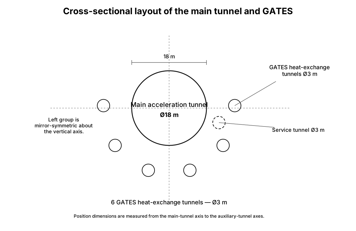
- One technical service tunnel (diameter 3 m). It is located separately, to the side of and below the axis of the main acceleration tunnel. It provides continuous diagnostic and repair access without stopping traffic. The GATES tunnels are designed for the combined effects of high internal pressure (up to 25 MPa), rock pressure, and dynamic loads. The entire seven-tunnel complex is excavated by a fully robotic fleet of micro-tunnel-boring machines (micro-TBMs). GATES physically and functionally separates the energy infrastructure from the transport infrastructure, providing exceptional reliability and maintainability.
Cooling system and Hydrothermal Trunk Canal
- Deep cooling circuit. GATES heat-exchange tunnels are arranged around the main acceleration tunnel, carrying a CO₂-based working fluid in a dense high-pressure or supercritical state. In the normal low-temperature mode, the target temperature of the cold stream before it enters the deep collectors is about +5…+15°C. After absorbing geothermal heat and passing through the deep section, the CO₂ may heat above +100°C depending on depth, rock heat flux, and the power-generation mode. The circuit removes geothermal heat, forms a cooled zone around the main tunnel, and allows the route to be built safely at depths of about 5–8 km. At +5…+15°C the CO₂ is compressed; in heated sections it is supercritical when both temperature and pressure exceed their critical values.
- Hydrothermal Trunk Canal (HTC). The canal follows the StarRoad route beside the service highway, power line and communications, joining the terminals into one surface heat-rejection system.
The HTC is a water channel approximately 5–8 m wide and 2–3 m deep. Several independent high-pressure serpentine pipelines run along its bed and carry CO₂ between adjacent terminals. Water acts as a thermal buffer and intermediate heat-transfer medium.
CO₂ enters the coils from turbines, heat exchangers or compressors at approximately +50…+80°C. Over an approximately 50 km interterminal section it transfers heat to the water and cools to about +22…+35°C, depending on season, humidity, rainfall, night-sky radiative cooling and canal operating mode.
Under normal operation, canal water remains around +22…+32°C, rising locally to +35…+45°C in hot sections. Brief local heating to +50…+80°C may occur near a hot-flow inlet and may suppress some biological activity, but the water is not potable without treatment.
Light selective covers over the canal reflect solar radiation while permitting infrared heat rejection.
- Terminal cooling. Each terminal contains cooling towers, heat exchangers, pumps, booster compressors, turboexpanders and reserve chillers. In normal operation, the HTC passively rejects most low-grade heat.
Cooling towers and terminal heat exchangers reduce the post-HTC CO₂ stream from roughly +22…+35°C to +15…+25°C. When required, reserve chillers lower it to −5…+5°C before the deep collectors. Chillers are peak, emergency or seasonal reserves rather than the continuous primary mode.
- Booster compression and turboexpansion. CO₂ reaches the next terminal cooled but at elevated pressure. It may then pass through a turboexpander, recovering part of the compression energy and cooling further through expansion to approximately −10…+5°C, depending on pressure, flow and required phase state.
The CO₂ then enters the GATES collectors at the required temperature, pressure and phase. This cycle does not create free energy: the compressor adds work, the canal rejects compression heat, and the turboexpander recovers only part of the input. Its benefit is a colder flow with less demand on active refrigeration.
- Redundancy and bidirectional flow. The serpentine lines are duplicated and bidirectional. If one circuit is damaged, flow is rerouted through a reserve pipe or adjacent terminal. Direction can change with thermal load, emergency state and section availability.
- Maintainability. Gates divide the HTC into approximately one-kilometre sections. A damaged section is isolated and pumped down to its minimum operating level or partly drained. After depressurization, crews or robots access the coils without stopping the full corridor. Reserve circuits, flow reversal, increased exchange through neighbouring terminals and temporary chiller operation maintain cooling during repairs.
- Limited water-management role. With a continuous east-to-west gradient, the HTC can sustain slow gravity flow, section flushing and controlled discharge of surplus water as a secondary function.
Night-time equatorial rain can refill the canal through catchments, settling basins, filters and overflows. Because the water never contacts CO₂ directly, local treatment can make it available for limited irrigation, terminal service water, firefighting reserves and green buffer zones.
Water use remains secondary and is permitted only where it does not compromise the HTC’s primary task: cooling CO₂ and maintaining GATES thermal stability.
- Importance to StarRoad. Deep collectors, the HTC, terminal coolers, cooling towers, booster compressors, turboexpanders and reserve chillers form one distributed thermal-management system. It reduces dependence on local refrigeration plants, improves fault tolerance, redistributes heat among terminals and makes deep accelerator construction more realistic.
The surface cooling system also strengthens StarRoad’s economic role: a linear belt of terminals, service roads, energy nodes, water infrastructure, industrial sites and irrigated agricultural zones develops along the route.
Integration with technical tunnels and surface terminals
- Integration with GATES. Collector tunnels are excavated an additional 10–20 m beneath every inclined access tunnel to pre-freeze and stabilize the rock during construction and later generate power.
- Surface terminal complex. Every inclined tunnel ends at a multifunction surface terminal. Each of the 40 terminals is an independent node containing:
- ventilation and gas cleaning to maintain tunnel air conditions and remove spent air;
- a construction base with areas for stockpiling, transshipment and temporary storage of modules, excavated material and supplies;
- an operations and accommodation building for shift staff, including control rooms, rest rooms, workshops and stores;
- a geothermal power station and cooling plant integrated into GATES to manage the heat-transfer fluid in the deep collectors;
- a CO₂ capture and processing station for Direct Air Capture (DAC), closing the GATES loop by liquefying and purifying captured CO₂ and feeding it to the deep collectors as the heat-transfer fluid;
- a connection point for external power grids and communications, including reserve power and broadband.
Strategic importance
Beyond power supply and thermal stabilization, the system makes safe and economical ultra-deep construction of the main accelerator—5–8 km or more—possible in principle. Active control of the thermal field and removal of geothermal heat overcome temperature limits that would otherwise prevent such depth. Deep construction in turn permits an optimal S-curve with large radii, providing a gradual climb and a gateway exit at approximately 5–6° while holding cargo and crew loads near 4g over the 2,050 km route. GATES is therefore the technical foundation not only of the power system but of StarRoad’s entire ballistic optimization. A fully robotic fleet of micro tunnel-boring machines excavates the complex.
Power and scale
- Cost of one 2.5 GW station: US$2.0–3.0 billion.
- Cost of 40 stations: US$80–120 billion.
The range uses the lower bound of Russian geothermal-plant costs—approximately US$650/kW based on Iturup—and an upper bound of US$1,500/kW for complex projects.
The calculation uses an upper estimate of 100 GW for total GATES capacity. Actual available power can be established only after geological exploration and may be far lower, potentially only several gigawatts. Funds released in that case would build alternative generation.
Environmental and regional functions
StarRoad follows a model of active environmental stewardship. As the permanent working fluid in the closed GATES circuit, supercritical CO₂ would make the project the world’s largest stationary user of atmospheric carbon dioxide. Millions of tonnes would be removed from atmospheric circulation and retained in the technical circuit for centuries, turning StarRoad into a climate-engineering instrument capable of offsetting emissions from entire industrial sectors.
The HTC is more than a GATES cooling component. It is transcontinental dual-use infrastructure that also benefits the region:
- Irrigation. Diversion gates allow canal water to irrigate farmland along the route, turning dry areas into an African ‘green belt.’
- Natural replenishment. Frequent equatorial downpours refill the canal.
- Gravity flow. The natural gradient from 3,400 m in the east to sea level in the west moves water without pumps and provides free circulation.
- Micro-hydropower. The elevation drop permits a cascade of small hydroelectric stations that supply additional renewable power to local grids and the corridor itself.
StarRoad thus becomes not only transport infrastructure but an agro-energy platform integrated into the region’s sustainable development.
GATES and the generating network supply surplus clean energy not only to the accelerator but also to nearby cities, industry and farms.
Perpendicular technical access-tunnel system
To support construction, ventilation, repair and evacuation, 40 inclined transport tunnels are built along the route at 50 km intervals. Each has a 30° inclination and a circular cross-section of Ø18 m. They are excavated by the same tunnel-boring machines as the main tunnel and connect the surface with the main corridor at depths of up to 8 km.
- Logistics. Each provides an independent evacuation route for staff and crew after an Alarm-2 emergency stop. Unlike a vertical shaft, an inclined tunnel allows self-propelled vehicles to evacuate dozens of people in one trip.
- Safety. The tunnels provide a second independent evacuation path for staff and crew after an Alarm-2 stop.
- Scalability. Inclined tunnels form connection points for future parallel StarRoad lines. Horizontal branches can be bored from them to new accelerator tunnels, turning the access network into an expanding transport framework.
- Integration with GATES. Collector tunnels 10–20 m deeper than each inclined tunnel pre-freeze and stabilize the rock during construction and later support power generation.
Surface terminal complex
Every inclined tunnel ends at a multifunction surface terminal. Each of the 40 terminals is an independent node containing:
- ventilation and gas-cleaning equipment that maintains tunnel air conditions and removes spent air;
- a construction base with space for stockpiling, transshipment and temporary storage of modules, spoil and building materials;
- an operations and accommodation building for shift workers, with control rooms, rest rooms, workshops and stores;
- a geothermal power station and cooling equipment integrated into GATES and managing the heat-transfer fluid in the deep collectors;
- a CO₂ capture and processing station using Direct Air Capture (DAC). Captured CO₂ is liquefied, purified and sent to the deep collectors as the GATES working fluid, closing the loop;
- connections to external power grids and communications, including reserve power and broadband;
- road or rail access linking the terminal to the regional transport network;
- an evacuation point at the surface with emergency medical facilities and a helipad.
Legal and environmental flexibility
The inclined geometry allows surface terminals to stand outside protected areas—national parks, reserves and watersheds—even where StarRoad itself passes deep beneath them. This removes the principal legal obstacle to routing under conservation areas and avoids building infrastructure inside park boundaries. Each terminal can occupy the nearest unprotected site and connect through an inclined shaft, simplifying approvals, reducing environmental pressure and eliminating direct impact on protected ecosystems.
Power supply and energy storage
The StarRoad accelerator uses a three-level electrical network providing:
- assured redundancy, so a single component failure does not stop operations;
- adaptive discharge times, from seconds near the start to microseconds near the end;
- minimum high-power cable length, reducing loss and inductance.
Topology levels
Level 0: primary storage at terminals
- Each of the 40 terminals has gravity storage, pumped-storage hydropower using the canal’s micro-hydro facilities, and lithium-ion battery energy storage systems (BESS).
- Total capacity per terminal: approximately 5–9 GWh; approximately 360 GWh along the full route.
- Output: high-voltage direct current, up to 100 kV, carried through trunk cables in the technical tunnel.
Level 1: segment controllers for 50 km sections
- The route is divided into 41 segments of approximately 50 km; the final segment is the 50 km approach to the gateway.
- Each segment has a main distribution controller supplied by two neighbouring terminals for cross-redundancy.
- The segment controller distributes and synchronizes energy among one-kilometre power blocks.
Level 2: one-kilometre power blocks
Each one-kilometre block has a local controller that:
- receives energy from the segment controller;
- controls buffer lithium-ion batteries beneath the main tunnel walls;
- controls switchable winding sets connected through flywheels and supercapacitors in dedicated recesses behind the tunnel walls.
Two independent channels from the segment controller to every kilometre block provide redundancy.
Cable-route architecture
- Trunk cables, Level 0→1. They run through a 3 m technical service tunnel parallel to and 3 m away from the main tunnel.
- Route distribution. Cables from each terminal extend 50 km in both directions, 100 km total, overlapping adjacent terminal zones. Every segment is therefore supplied by at least two neighbouring terminals, providing 100% redundancy.
- Entry into the main tunnel. At one-kilometre intervals, cables pass from the technical tunnel through sealed penetrations into the main tunnel and connect to the local block controller.
- Distribution within each block. Downstream of the controller, power divides into two parallel paths:
- Path A: buffer lithium-ion batteries with approximately 50–120 MWh per block, smoothing second-scale peaks.
- Path B: switchable winding sets supplied through flywheel stores and supercapacitors installed behind the tunnel walls.
Three-zone adaptation of discharge rate
The acceleration profile gives each winding set its highest peak power near the start, where ultrashort pulses are unnecessary, and reduces demand toward the route’s end. Different storage and switching technologies can therefore serve different zones:
| Zone | Route section | Discharge timescale | Storage and switching technology | Reason |
|---|---|---|---|---|
| Zone I: low speed | 0–200 km | Seconds to milliseconds | Lithium-ion batteries and standard IGBT inverters | The shuttle is slow and takes more than 0.1 s to cross one kilometre; BESS can feed the windings without intermediate buffers. |
| Zone II: medium speed | 200–1,000 km | Milliseconds to microseconds | Buffer lithium-ion batteries, inertial flywheels and SiC inverters | The shuttle is accelerating and switching must be faster, but mechanical flywheels remain practical. |
| Zone III: high speed | 1,000–2,000 km | Microsecond pulses | Supercapacitors and fast GTO/IGCT thyristor switches | Transit time per kilometre falls to 0.09 s. Only supercapacitors with nanosecond response can stabilize the pulse. |
Important: Zone III requires less energy per kilometre than Zone I because acceleration is tapering. Component loads therefore decline even though the required discharge rate is faster.
Redundancy and emergency resilience
- Controller duplication. Every segment and kilometre controller has a hot standby: two identical boards with independent power.
- Cross-feeding. Every kilometre block can receive energy from its own segment controller or from neighbouring controllers through reserve cables in the technical tunnel.
- Local winding redundancy. Each kilometre block has three independently switched winding sets. If one is damaged, the other two continue accelerating the shuttle at lower efficiency without stopping it.
- Emergency isolation. If a short circuit or overheating is detected, the kilometre controller disconnects its block and isolates it with inter-section gates without affecting adjacent blocks.
Physical implementation and summary
| Element | Location | Function |
|---|---|---|
| Primary storage | Surface terminals | Long-duration energy storage: 360 GWh. |
| Trunk cables | Three-metre technical tunnel | Redundant power transmission from terminals to segments. |
| Segment controllers | Main-tunnel recesses every 50 km | Power distribution to kilometre-long blocks and synchronization. |
| Buffer lithium-ion batteries | Beneath the main tunnel walls | Smoothing second-scale peaks in Zones I and II. |
| Flywheels | Behind the tunnel walls in Zone II | Buffering millisecond-scale pulses. |
| Supercapacitors | Behind the tunnel walls in Zone III | Microsecond stabilization and compensation for voltage dips. |
| Local kilometre controllers | Recesses every kilometre | Winding switching, condition monitoring and buffer control. |
| Accelerator windings | Inner tunnel surface | Creation of the travelling magnetic field that accelerates the shuttle. |
Advantages of the power architecture
- Smooth load distribution. Peak power is not required along the entire tunnel at once: pulses are slower at the start and shorter but less energetic near the end.
- Redundancy at every level. Failure of one terminal, controller or even a complete 50 km segment does not stop the system; neighbouring terminals and segments cover the deficit.
- Scalable expansion. New parallel StarRoad lines require no power-system rebuild; additional trunk cables can be installed in the existing technical tunnel.
- Cost optimization. Expensive supercapacitors and flywheels are used only where needed near the final sections, while cheaper lithium-ion batteries serve the beginning of the route.